
A stainless fitting that survives furnace heat may still struggle with the fluid inside it. When you specify 310S stainless steel, service conditions matter as much as the temperature on the equipment nameplate.
This grade offers strong high-temperature oxidation resistance, but machining it requires control of work hardening, heat, and chips. Start with its composition, then match its properties and manufacturing requirements to the finished component.
What Is 310S Stainless Steel?
310S is an austenitic chromium-nickel stainless steel, identified as UNS S31008. Its high chromium and nickel content makes it useful for heat-resistant equipment.
Composition and the austenitic structure
The principal composition limits explain the grade’s character.
| Element | Specified content | Main contribution |
|---|---|---|
| Chromium | 24% to 26% | Supports oxidation resistance and the protective surface film |
| Nickel | 19% to 22% | Supports the austenitic structure and high-temperature performance |
| Carbon | 0.08% maximum | Limits carbide formation compared with standard 310 |
Austenitic describes the metal’s internal structure. For manufacturers, the practical benefits include useful ductility, formability, and weldability.
However, the grade cannot be hardened through conventional quenching. Cold work can increase hardness and strength, so incoming stock condition affects machining behavior.
How 310S differs from 310 and 310H
Standard 310, designated UNS S31000, permits carbon up to 0.25%. Penn Stainless documents these 310 versus 310S carbon limits.
Lower carbon reduces the tendency for chromium carbides to form during welding or relevant thermal exposure. These carbides can leave adjacent grain-boundary regions depleted in chromium, a condition called sensitization.
The lower carbon content doesn’t materially improve oxidation resistance over 310. Also, 310H has separately controlled carbon limits for high-temperature strength considerations. Don’t substitute among these grades without reviewing the drawing and governing specification.
High-Temperature Properties Need Service Limits
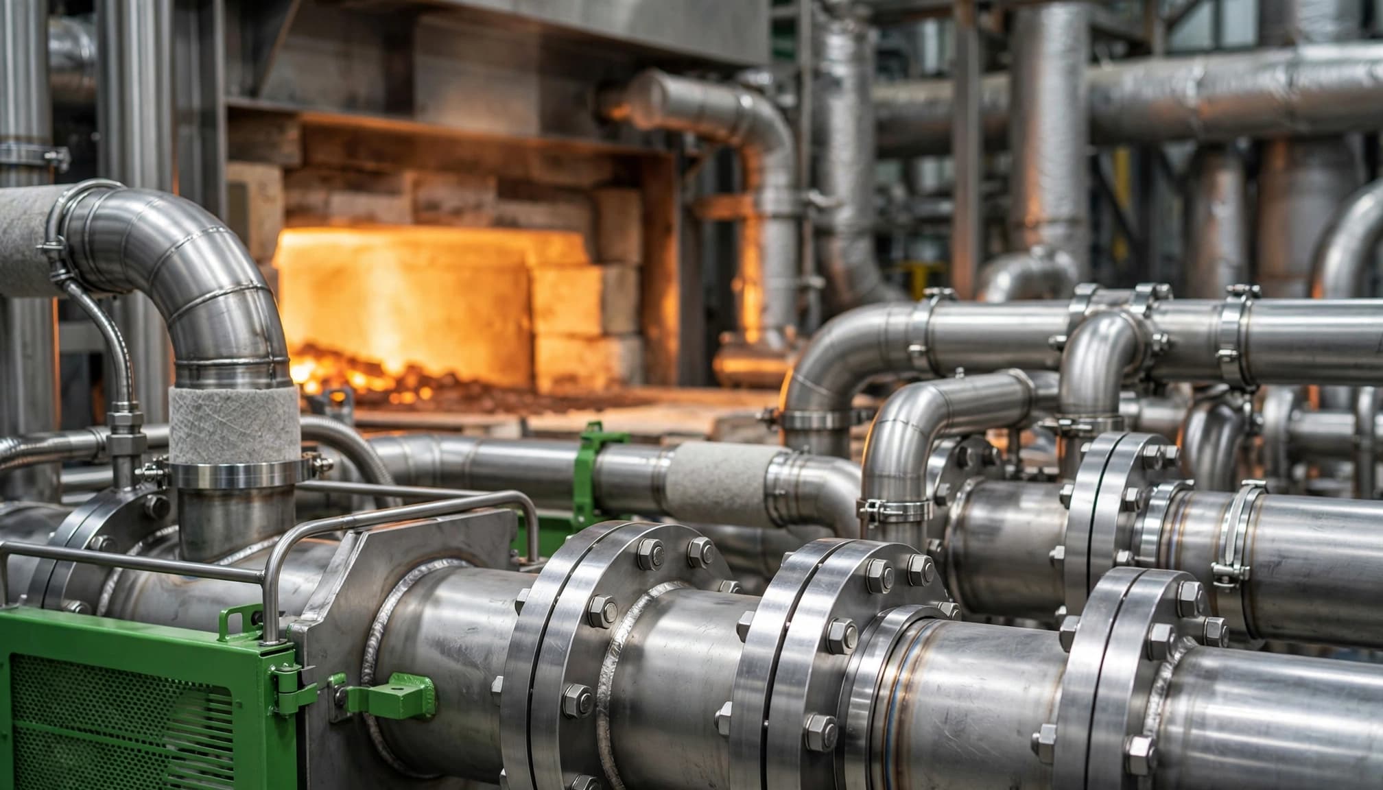
Temperature ratings describe particular exposure conditions. They don’t establish the safe operating limit of every component.
Oxidation resistance depends on the atmosphere
Aperam lists 1,050°C (1,922°F) for continuous service and 1,100°C (2,012°F) for peak or intermittent exposure. Those values apply to atmospheres containing sulfur up to 2 g/m³.
For higher sulfur content, Aperam lowers its stated maximum to 950°C (1,742°F). Less-oxidizing, carburizing, nitriding, or sulfurizing atmospheres also require separate review.
Other suppliers publish different limits because exposure assumptions and thermal cycling differ. AZoM’s 310S grade overview provides additional property context, but the relevant producer’s guidance should govern material selection.
An oxidation-resistance temperature is not a pressure rating. A fitting also needs acceptable strength, creep resistance, and joint performance at operating temperature.
Strength data require the right basis
Aperam Brasil reports typical 310S values of 580 MPa tensile strength, 280 MPa yield strength, and 50% elongation. Its typical hardness figure is 80 HRB.
These are datasheet values, not guaranteed minimums for every bar or finished part. Confirm product form, delivery condition, and test basis before using them.
At elevated temperatures, creep becomes a design concern: sustained loading can gradually deform metal. Therefore, room-temperature strength alone cannot establish allowable stress for a hot fitting.
Thermal expansion also affects assembly clearances and sealing. Evaluate heating cycles, connected materials, and mechanical restraint alongside the alloy.
Corrosion Resistance Depends on the Actual Exposure
High-temperature oxidation resistance concerns reaction with hot gases and the formation of protective surface oxides. Wet corrosion involves different mechanisms and operating conditions.
Although 310S stainless steel contains substantial chromium and nickel, it isn’t a universal solution for acids, chlorides, or contaminated condensate. Its low carbon content reduces sensitization risk without eliminating every form of corrosion.
For a fluid-system component, review the process fluid, contaminants, cleaning chemicals, and operating temperature. Also consider shutdown conditions, when cooling equipment may collect condensate.
Crevices beneath seals and deposits can retain liquid after exposed surfaces dry. Consequently, an attractive exterior finish says little about corrosion inside a trapped-fluid region.
Common applications include furnace components, radiant tubes, and heat-treatment equipment. Machined connectors or fittings around such equipment need an application-specific review before production.
When ordering custom CNC-machined fluid fittings, identify whether hot-gas exposure, internal fluid compatibility, or pressure-bearing duty drives the material choice. These requirements may point toward different alloys.
Also review any welding or post-machining heating steps because they change the component’s thermal history and surface condition.
CNC Machining 310S Stainless Steel Fittings
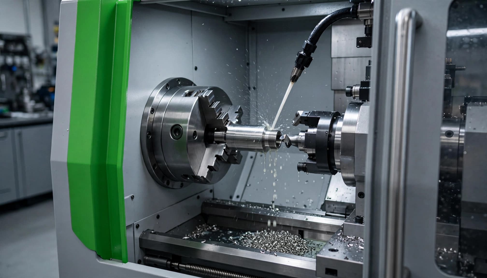
310S can be turned, milled, and drilled with conventional CNC equipment. However, its toughness and work-hardening tendency make stable cutting conditions important.
Control work hardening through tooling and support
Work hardening occurs when deformation makes the surface layer harder. A dull edge that pushes or rubs can leave tougher material for the following pass.
Use sharp tooling and geometry intended for austenitic stainless steel. Coated carbide is a common production choice, but insert grade and edge preparation depend on the operation and setup.
Keep tool overhang short, support slender features, and avoid dwelling against the workpiece. Plan a finishing cut that removes material consistently rather than repeated rubbing passes.
Sandvik Coromant’s workpiece material guidance discusses the cutting behavior of austenitic stainless steels. Wisense’s guide to CNC machining stainless steel provides broader process context.
Set speeds and feeds for the actual operation
Begin with the toolmaker’s guidance for the insert, material group, and operation. There is no universal 310S cutting-speed or feed setting.
Cutting speed affects heat and tool wear. Meanwhile, feed and depth of cut must produce a stable chip within the chipbreaker’s operating range.
Adjust against stock condition, machine rigidity, coolant delivery, and measured results. A short, rigid fitting body won’t necessarily accept the same settings as a thin sleeve.
Monitor chip shape, edge wear, finish, and dimensional drift. For thread turning, feed must match the specified thread lead; adjust cutting speed and pass strategy accordingly.
Control Chips, Coolant, and Internal Features
Fittings combine exposed surfaces with difficult-to-inspect internal passages. Therefore, chip evacuation and burr control deserve their own process plan.
Deliver coolant where cutting occurs
Direct coolant into the cutting zone, rather than onto the outside of a chip nest. Consistent delivery helps manage heat and move chips away from the edge.
Match the chipbreaker to the feed, depth of cut, and operation. Long chips can wrap around tooling, obstruct coolant, or score a finished seal land.
If chip control deteriorates, inspect the edge and setup before increasing speed. Worn tools, unsuitable feeds, and poor coolant access can produce similar symptoms.
For drilling, choose a coolant and evacuation strategy suited to hole diameter and depth. Sandvik’s drilling and chip-evacuation guidance explains why coolant access and chip clearance need attention.
Protect bores, threads, and sealing faces
Turning suits fitting bodies with concentric bores, seats, and threads. Milling adds wrench flats, slots, and side ports; operation order should preserve the required feature relationships.
Deep holes require active monitoring for chip packing. Don’t wait for tool breakage to reveal an evacuation problem.
Cross-holes can leave burrs inside the flow path even when the exterior looks clean. Define which intersections require deburring and how inspection will verify them.
Also check thin-walled parts after unclamping. Excessive holding force can distort a bore during machining, then release that distortion during inspection or assembly.
Specify Stock, Cleanliness, and Production Acceptance
A reliable order needs more than “310S stainless.” State UNS S31008, the applicable product standard, product form, delivery condition, and material-certification requirements.
Bar stock for machined fittings and plate for fabricated equipment follow different purchasing requirements. Consequently, plate datasheet figures shouldn’t become automatic acceptance limits for a turned component.
Define the features that control function
Identify critical datums, thread requirements, seal lands, mating bores, and internal passages. Apply tight tolerances and surface requirements where they affect assembly, leakage, or flow.
For precision CNC lathe machining, provide geometry, quantity, inspection requirements, and material condition together. This gives the manufacturer a clearer basis for process planning.
If leak testing is required, specify the medium, pressure, duration, and acceptance criteria. Dimensional inspection alone doesn’t prove sealing performance.
Keep surfaces clean and validate sustained production
Separate finished stainless components from carbon-steel grinding debris. Use suitable cleaning and handling practices to avoid embedded iron, residual coolant, and loose chips.
Where required, define passivation and its acceptance criteria. Passivation cannot correct an unsuitable alloy choice, remove burrs, or eliminate a fluid-trapping crevice. Heat tint may require a separate removal process.
Finally, validate a sustained production run rather than one successful sample. Track tool wear, dimensional drift, burr formation, and sealing-surface damage across the intended inspection interval.
Retain batch traceability and segregate nonconforming components before shipment.
Key Takeaways
- 310S combines high chromium and nickel content with a lower carbon limit than standard 310.
- Its oxidation resistance requires atmosphere-specific temperature limits and a separate mechanical design review.
- CNC machining needs sharp tooling, stable engagement, effective coolant delivery, and controlled chips.
- Stock certification, internal deburring, surface cleanliness, and sustained-run inspection support repeatable fitting production.
Frequently Asked Questions
Is 310S better than 310 for every high-temperature part?
The grades share similar oxidation resistance. Lower carbon makes 310S useful when limiting sensitization matters, but long-term loaded service may require different carbon and strength requirements. Selection depends on thermal exposure, fabrication, and the applicable design rules.
Can ordinary CNC machines produce 310S fittings?
Yes, provided the equipment, tooling, and setup can meet the drawing requirements. Geometry, stock condition, workholding, coolant access, and chip evacuation determine a workable process. Confirm tool life and dimensional stability over production, rather than accepting one good first piece.
Match Heat Resistance to the Finished Fitting
310S stainless steel is useful when its oxidation resistance matches the actual atmosphere and temperature. A dependable fitting also needs compatible fluid exposure and an appropriate mechanical design.
For machining, prioritize a stable cutting process and clean functional surfaces. Clear stock requirements and production validation help preserve those advantages in the finished component.
